Building

Follow theese instructions assemble the device and to build and upload both FE310 and ESP32 firmware.

1 Install prerequisites

You will need the following software available on your machine:

  • git
  • GNU Make
  • RISC-V GNU Toolchain
  • RISC-V OpenOCD
  • ESP-IDF from Espressif

Binary RISC-V GNU Toolchain and OpenOCD are available from SiFive at https://github.com/sifive/freedom-tools/releases

Download and unpack the archives for your platform and export RISCV_PATH and RISCV_OPENOCD_PATH variables:


export RISCV_PATH=/path/to/riscv64-gcc
export RISCV_OPENOCD_PATH=/path/to/riscv-openocd

To install ESP-IDF follow instructions from ESP-IDF Programming Guide. Install version 4.2 or later.

2 Obtain source

git repository can be cloned by running the following command:


git clone https://git.majstor.org/rvPhone.git

Repository contains following directories:

  • hw/rvPhone: KiCad project that contains main board schematics and layout
  • hw/display: KiCad project that contains display adapter board schematics and layout
  • hw/prog: KiCad project that contains FT2232H-56Q adapter board schematics and layout
  • fw/fe310: Firmware for Freedom E310 SoC
  • fw/esp32: Firmware for Espressif ESP32 SoC
  • yocto: yocto layer with BSP for CL-SOM-iMX8
  • ecp: ecp library

3 Assemble

To assemble the phone you will need:

  • main and display adapter boards built from hw/rvPhone and hw/display KiCad projects
  • E50RG84885LWAM520-CA display
  • SIMCom SIM7600X-H mini PCIe module
  • Any Li-Ion or Li-Po 3.6/3.7V battery

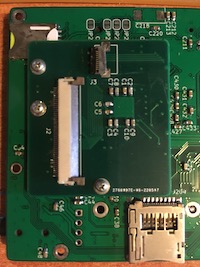
Locate DISPLAY connector at the bootom side of the board and connect display adapter board to it:

display adapter

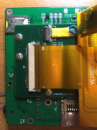
Connect display panel to J2 and J3 connectors on display adapter board:

display panel

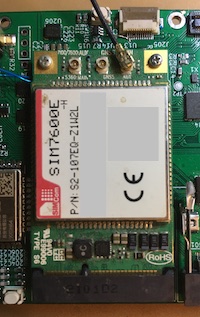
Insert cellular modem into mini PCIe connector:

modem

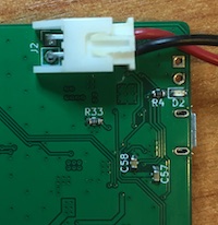
Locate BAT connector at the bootom side of the board and connect battery to it:

battery

4 Connect JTAG/UART programmer

This device supports FT2232H-56Q Mini Module for flashing both FE310 and ESP32 firmware. Connect FT2232H-56Q to J205 connector using FFC breakout board according to folowing table:

J205 Pin FT2232H-56Q Pin
1. ESP32.UART0.RXD BD0
2. ESP32.UART0.TXD BD1
3. GND GND
4. JTAG_TCK AD0
5. JTAG_TDO AD2
6. JTAG_TMS AD3
7. JTAG_TDI AD1
8. JTAG_TRST_N AD5

Leave other pins unconnected.

Alternatively, you can make FT2232H-56Q adapter board from hw/prog KiCad project directory and connect it using 12 conductor 0.5mm pitch FFC jumper cable.

5 Compile and upload firmware

To build firmware for FE310 run follwing commands:


cd <path to repository>/fw/fe310
make
cd phone
make upload_ftdi

To build firmware for ESP32 run following commands:


cd <path to repository>/fw/esp32
make menuconfig
make
make flash

In make menuconfig, please make sure that Enable PPP support is selected under Component config -> LWIP menu and that Notify Phase Callback, PAP Support and CHAP Support are selected under PPP menu.

Before flashing ESP32 device you must put it into programming mode:

  • press and hold WAKE button (SW2 - on the left side of the board)
  • push ESP32 reset switch (SW201 - bottom right)